In these passages from the Pneumatica, Hero of Alexandria describes two different pneumatic organs: an altar organ operated manually and a second instrument driven by wind power through a mechanism similar to a windmill. The text details the systems for compressing and distributing air, focusing on pistons, valves, hydraulic reservoirs, ducts and devices for opening the sounding pipes. Of particular interest is the description of the pipe-control mechanisms, in which primitive forms of keyboard and automatic air-supply systems applied to musical production can be recognised.
76. An altar organ operated manually
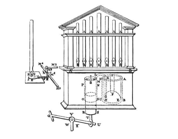
Let ABCD (fig. 76) be a small bronze altar containing water. In the water let an inverted hollow hemisphere, called the pnigeus, EFGH, be placed, allowing the passage of water at the bottom. From the top of this, communicating with it, let two pipes rise above the altar; one of them, GKLM, bent outside the altar and communicating with an inverted box, NXOP, whose inner surface is perfectly levelled to house a piston. In this box let the piston RS be inserted with care, so that no air enters laterally; and to the piston let a rod, TU, of great strength be attached. Further, let another rod, UQ, be attached to the piston rod, which moves about a pivot at U, and which also acts as the beam of a lever on the vertical rod WY, which must be well fixed. On the inverted bottom of the box NXOP let another smaller box, Z, be placed, communicating with NXOP and closed by an upper lid: in the lid there is a hole through which air will enter the box. Let a thin plate be placed under the hole in the lid to close it, held by four pins passing through holes in the plate and having heads so that the plate cannot fall: such a plate is called a valve. Further, let another pipe, FI, rise from FG, communicating with a transverse pipe, A′B′, on which rest the pipes A, A, A, communicating with the pipe and having at their lower ends small boxes, like those used for money; these boxes communicate with the pipes and their orifices B, B, B, must be open. Through these orifices let perforated covers slide, so that when the covers are pushed in, the holes in them coincide with the holes in the pipes, but when the covers are drawn out, the connection is broken and the pipes are closed. Now, if the cross-beam UQ is pressed at Q, the piston RS will rise and force out the air in the box NXOP; the air will close the opening in the small box Z by means of the valve described above and will pass along the pipe MLKG into the hemisphere: again it will pass out of the hemisphere along the pipe FI into the transverse pipe A′B′ and out of the transverse pipe into the pipes, if the openings in the pipes and covers coincide, that is if the covers, all or some of them, have been pushed in.
So that, when we wish any one of the pipes to sound, the corresponding holes may be opened and closed when we wish the sound to cease, we may use the following device. Imagine that one of the boxes at the ends of the pipes, CD, is isolated, D being its orifice, E the communicating pipe, RS the cover applied to it and G the hole in the cover not coinciding with the pipe E. Take three jointed bars FH, HM, MM², of which the bar FH is fixed to the cover SF, while the whole moves about a pivot at M³. Now, if we press, with the hand, the end M² toward D, the orifice of the box, we shall push the cover inward and, when it is inside, the opening in it will coincide with that in the pipe. So that, when we withdraw the hand, the cover may be drawn out spontaneously and close the communication, we may use the following device. Under the boxes let a rod, M⁴M⁵, slide, equal and parallel to the pipe A′B′, and let elastic curved strips of horn be fixed to this, of which M⁶, in front of CD, is one. A cord, fixed to the end of the horn strip, is passed around the end H, so that when the cover is once pushed out, the cord becomes taut; if, therefore, we press the end M² and push the cover inward, the cord will forcibly pull the horn strip and straighten it, but when the hand is withdrawn, the horn will return to its original position and drive the cover away from the orifice, thus destroying the correspondence between the holes. This device being applied to the box of every pipe, when we wish a pipe to sound, we must press the corresponding key with the fingers; and when we wish one of the sounds to cease, remove the fingers, whereupon the covers will be drawn out and the pipes will cease to sound.
The water is poured into the altar so that the surplus air (I mean, of course, that which is forced out of the box and pushes the water upwards) may be confined in the hemisphere, so that the pipes that are free to sound may always have a supply. The piston RS, when raised, forces the air out of the box into the hemisphere, as has been explained; and when pressed down, opens the valve in the small box Z. In this way the box is filled with air from outside, which the piston, when pushed up again, will again force into the hemisphere. It would be better if the rod TU moved about a pivot at T, by means of a single [ring] R, which can be inserted into the lower part of the piston and through which the pivot must pass, so that the piston cannot be pulled sideways, but may rise and descend vertically.
77. An altar organ driven by the action of a windmill.
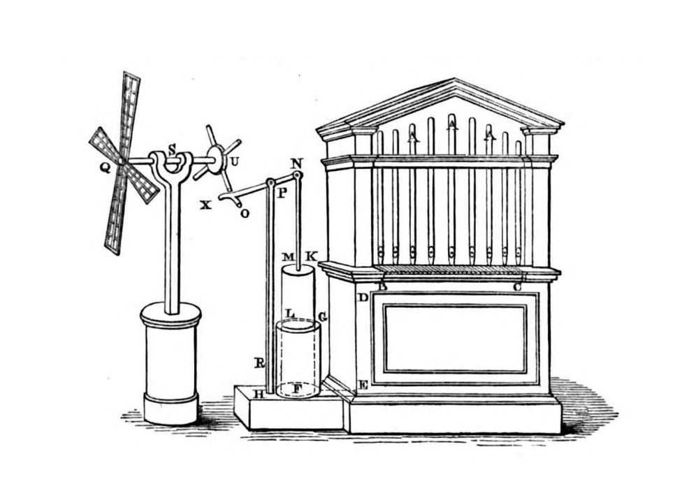
The construction of an organ from which, when the wind blows, the sound of a flute is produced. Let A, A, A (fig. 77) be the pipes; BC the transverse pipe communicating with them; DE the vertical pipe; and EF another transverse pipe leading from DE into a box GH, whose inner surface is made uniform to fit a piston.
In this box let the piston KL be inserted, which can descend freely within it. To the piston is fixed a rod MN, and to this another, NX, which acts on the rod PR. At N let there be a pivot that moves freely, and at the end X let a small plate XO be fixed, near which a rod S must be placed, movable on iron pivots inserted in a frame that can be shifted.
To the rod S let two small wheels, U and Q, be fixed: wheel U is fitted with pins arranged near the plate XO, while wheel Q has wide vanes similar to those of a windmill. When all these vanes, driven by the wind, cause wheel Q to rotate, rod S will turn, so that wheel U and the pins fixed to it will strike at intervals the plate XO raising the piston; when the pin moves away, the piston, descending, will force the air contained in the box GH into the pipes and thus into the pipes, producing sound.
We can always orient the frame that holds rod S toward the prevailing wind, so that the rotation may be faster and more uniform.